Tuesday, 2 June 2020

iPod classic wont charge from wall USB mains power adaptor  

iPod classic wont charge from wall USB mains power adaptor  

I repair ipod video and classic models and this is an issue that I get asked frequently, 'can you repair my ipod classic, it will not charge from a USB power supply, even a genuine Apple one'.  

If you have an ipod classic that will not charge from a wall outlet / adaptor but will charge when connected to your computer the problem is not with your ipod, it is just that this model is designed only to charge with specific Apple made chargers or some third party chargers of that era. These are often long since lost or discarded. Modern Apple or third party chargers will not work.

I have designed and built a small adaptor that solves this problem, it connects between any USB wall outlet / adaptor and your ipod 30 pin charge lead allowing it to charge ipods of this type.

These are available from my ebay listing.


The models that are affected by this charging behaviour are listed below.

6th Gen 80Gb MB029 MB147 

6th Gen 160Gb MB145 MB150 PB145 PB150


https://www.youtube.com/watch?v=99WBqPqBXpE


Sunday, 9 October 2016

Wizboard hoverboard segwway scooter gyro board repair.

Component transfer service: 

I thought I would offer a service to transfer gyro board parts over as I still can't see any Wizboard configured Gyro boards for sale. If you have faulty gyro boards and want your replacements modifying to fit your wizboard, leave a comment below with your email and I will get back to you !


I was passed a Wizboard branded balance board for repair, the first one I had seen.

A quick look on the web showed how it should work, no front lights should come on until you stand on the pressure pad. This one was powering on with both lights immediately on. The motors would not energise at all.

Again the web showed this was a fairly common failure, the solution being to replace the gyro board for each affected side.

I found this a little strange as I would not have expected both to fail at the same time ? and also wondered about the failure mechanism, especially as it is common fault ?

Nothing was showing up about 'repairing' the board, just swapping them out.

I didn't want to spend too much time as the person wanted the board back working ASAP and there was a quick solution but I thought I would at least have a bit of a look into it.

As a quick first check I checked the pressure pad switches were working correctly, they were.(no voltage across the connector, press the switch and it had about 3v across it).

The board doesn't have a great deal on it, a 3 axis chip, a microcontroller, a fet and voltage regulator, some passives.

All the passives, fet and regulator checked out so my money was on the 3 axis chip, the micro second but as there was no way to flash a new one I just went with the 3 axis chip.

I ordered 2 new chips and swapped them out, chips were removed using hot air and flux, and replaced the same way, touching in with the iron afterwards as I didn't want to overheat the chip. What is going on inside a 3 axis chip to sense movement ! its like magic, I will have to read up on it.

Sadly no success, board behaved exactly as before, disappointment.

So two new boards were sourced off ebay, cheapest price was £32 for two delivered.

There were no identical boards, the Wizboard does not have opto sensors mounted on the board, the switches are mounted in the pad and connect via wires, however the layout and components on the ebay boards looked almost identical except for this so I ordered some with a view to swapping parts over.

The boards came and a close inspection revealed a few of the resistors (for LED current limiting) were a different value.

Also although the connectors on the board looked the same the Wizboard wiring would not plug into them as the molding was different.

So as well as swapping the sensor connectors over, I swapped all the other connectors and the SMD resistors for the LED's.

Put it all back together ( had to open up the holes on the new PCB as they were about 0.5mm out of alignment).

Success ! it was nice to see the board back up and running, I had a quick go before handing it back !

I would have liked to have had a proper go at diagnosing and fixing the original boards, but if as I suspect it was the micro, it would have been more work to source the code and flash it (if available at all).

If you have had success actually repairing the boards or why they fail I would be very interested to know !

Wednesday, 3 December 2014

Technics SC-CH900

Not really a repair, but possibly useful info for somebody and an excuse to share some love for the SC-CH900, for me the best, the pinnacle of the mini hifi system in the 90's. Im sure a sony MHC-6600 fan would disagree :-)


So the Technics SC-CH900, I lusted after this baby for 23 years ! I always had a fascination and interest in home electronics, hi fi's TV's etc so back in 1991 after I started work I set about saving for and buying my first stereo. I knew all about HiFi, what cable to buy etc but despite it not being 'HiFi' in the seperates and OFC speaker cable sense I was hooked on getting one of these. I think it was the copious use of VFD displays that did it. So every week I would check out the stereos in the local shopping precinct, It was between the Technics and a Sony MHC3600/5600/6600. So the time came to buy, what I actually bought was a SC-CH700, largely the same system but without Dolby surround capability or the brushed metal finish. Crucially though it was from memory about £200-£300 less than the £1000 of the 900, a lot of money for me in 1992. The CH700 did me many years of good service and I loved it but I always regretted not getting the top of the tree 900. So good old eBay delivered the goods and all these years later I have a pristine SC-CH900 and I love it.

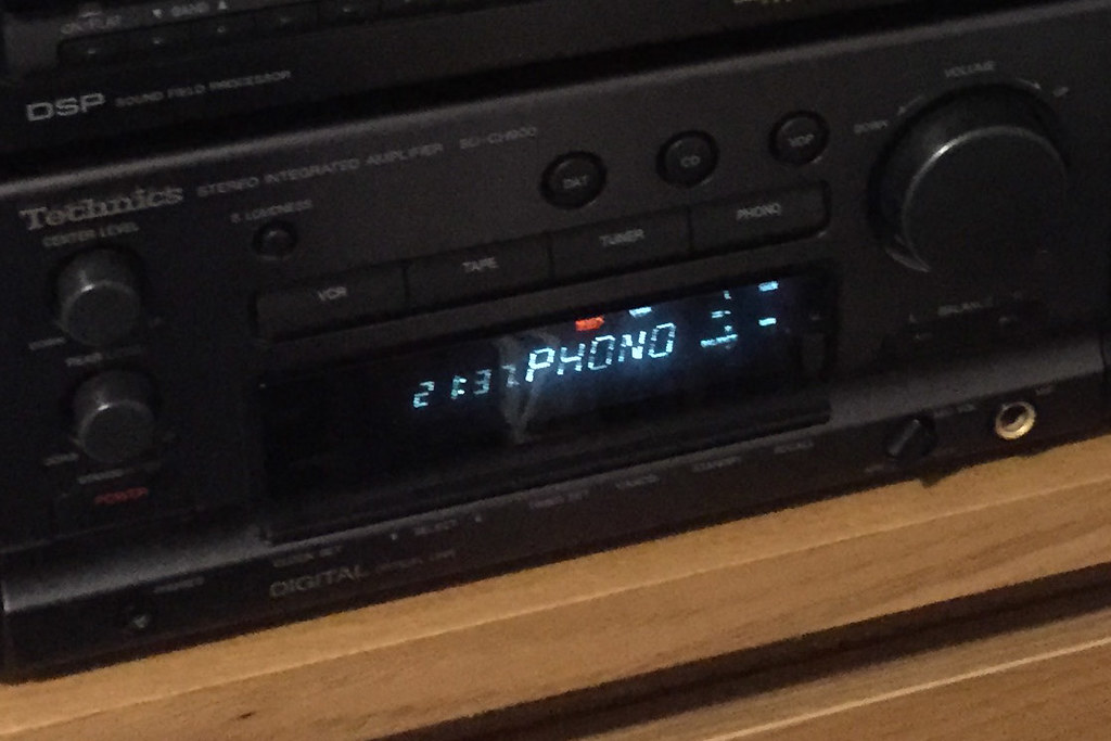
The only issue with it was the display of the main amp unit, the other components looked as new but the amp had 2 issues, the cover / filter over the VFD was cloudy / hazy / dirty. Secondly some parts of the display were significantly brighter than other, some looked over bright, others too dim ? As seen in the picture below from just after I bought it.


I looked into getting a new display and considered swapping the display from my 700. Panasonic UK said that they did not support the unit anymore but armed with a part number from the service manual I inquired in the US and found it was still available, would have cost about £40.

I did a bit googling on VFD's and found some referance to the grid wires oxidising due to lack of use. Either manually powering them and flowing a bit more than normal current through them may help or just leaving the unit in for an extended length of time. Although the clock is lit all the time it didnt seem to be getting any better after a week in standby so I left it fully powered on overnight. Success, the next day the display was bright and uniform.

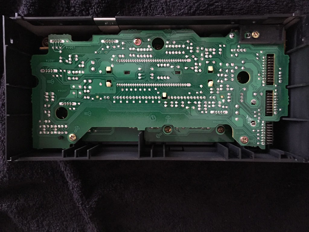
So I then stripped the unit down to clean the inside of the display, as the amp is on all the time in standby and has a fan running when the volume is turned up I suspect that is why it had got dirty and the other components looked like new.

I wasn't dissapointed with the construction, the service manuals are amazing in quality and the unit was too. It came apart very nicely, lots of screws, no forcing or plastic tabs breaking.


A careful gentle wipe and it was like new again.


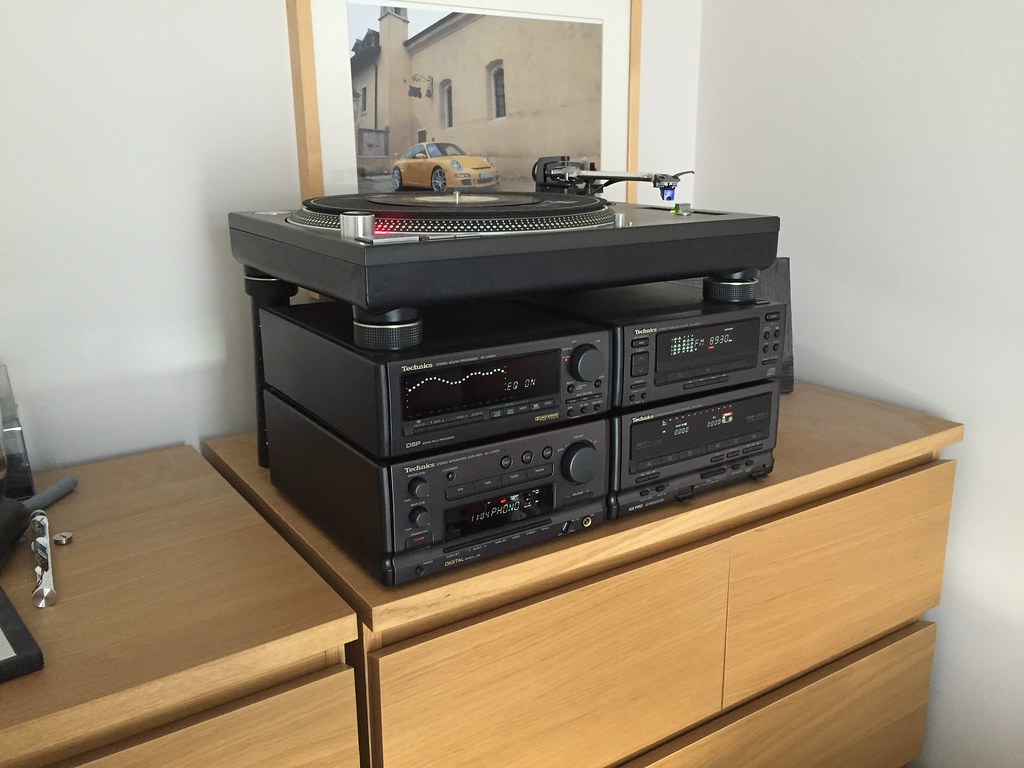
All set up with my SL1210 MK3D. A video of it in action.


http://youtu.be/_xItB0q_CI0

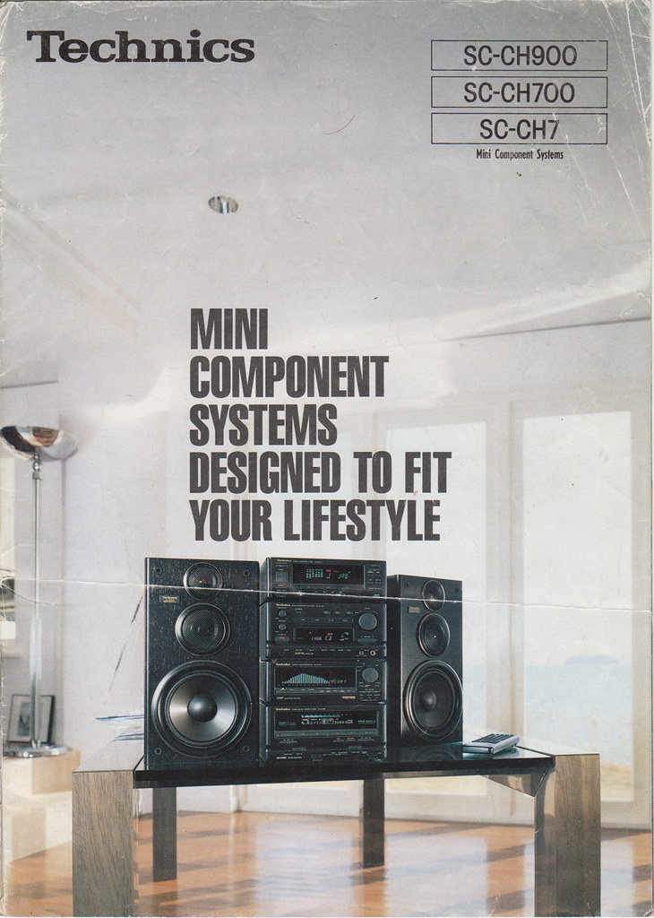
I knew I had the brochure sat in my loft somewhere so dug it out and scanned it below, ah the memories.


A link to the whole brochure I scanned in.

https://www.flickr.com/photos/120943638@N03/sets/72157649178929430/

The only other issues I have come across with these systems relates to the fan, when the volume goes above a certain level an internal fan kicks in, if this fails the unit shuts down. My SC-CH700 did this and I fitted a new, quiter fan. The 900 seems ok so far (and I am actually just useing hte the whole thing as a pre amp currently).

The fan was my only gripe with the 700 as I found it intrusive the way it would come in and out, almost with the beat at the volume levels I listened to the unit at.


Thursday, 30 October 2014

Panasonic SA PT470 dead, no power.

A Panasonic home theatre system, passed to me as dead no power.

A close listen revealed that the unit was not totally dead, pressing the power button the unit would click on then immediately off (but nothing on the display). This could be repeated a second time but then the unit would not respond. Pulling the power lead would allow this sequence to be repeated.

So the unit was alive and intelligent.

A quick google gave me the manual to download from the excellent site, electrotanya.

http://elektrotanya.com/panasonic_sa-pt470.pdf/download.html

Panasonic / Technics manuals are absolutely superb.

I may do a post about my beautiful Technics SC-CH900 that I finally bought after 22 years ! :-)  anyway..


So I opened it up and stated to take a look. Nothing obvious so decided the best plan of attack was to take the PSU out to get some proper access.

Admission: I took a stonking 360v dc hit from the main cap, Warning,  always approach with caution, measure the high voltage DC caps, and discharge as appropriate.

This fault will leave the main caps charged. I usually check but got sloppy.


So nothing jumped out visually, the mains went through a hefty filter and feeds standby power section of the PSU, the main psu is switched in through a relay, the relay only stays in if the PSU behaves correctly.

I did some passive checking but again nothing jumping out.

A move not without risks but I decided the best way forwards was to bypass the relay and see what wasn't powering up, the brain was obviously not happy and shutting everything down.

Using the drawings I checked all the rails and found the 18v fan power to be absent. I checked the rectifier diode D5805 and found it short. Fitted a repalcement and all good.


Friday, 22 August 2014

BMW E83 X3 PDC fault finding and sensor replacement. 66206989069


The PDC enables as you engage reverse and you are met by a long tone and then no PDC function, indicating there is a fault.

To check the sensors the engine does not have to be running, just but the ignition to second position so the dash lights up and press the PDC button. The long tone will sound. You can now get out to check the sensors.

Put your ear close to each one in turn, you should hear a very faint ticking sound. Any that don't are bad or have a wiring fault. In my experience the sensors do just go faulty, that is ones that look pristine and have clean electrical connectors can just stop working.

Order a replacement sensor. 66206989069 from ebay, £10 delivered

I had a search of the web about removing and refitting the sensors and didn't find a lot of encouragement, some indication of having to remove the bumper.

I can tell you on a model with unpainted bumpers it is possible to replace the rear inner sensors without having to take the bumper off because this is the one I did.

To replace the RHS inner sensor.

Remove the tow hitch cover.

Reach you hand in the gap to the back of the sensor.

Feel for the plug, squeeze and remove the electrical connector, this is in line with the body of the sensor but at the top.

The sensor can now be removed, tricky working blind but quite doable.

The sensor is held into the bumper receptacle with two fingers. Splay the two fingers downward and pull the sensor out. Theses fingers hold onto plastic pips on the sensor holding it in place. The fingers are quite flexible, my tip is to grip the body in the palm of your hand, splay one finger downward and pull on the sensor at the same time, then while still maintaining a pulling force on the sensor (this keeps the pip out of the finger ), splay the other finger. The sensor should then start to pull out from the rear.

Slide the new one in paying attention to the orientation.

My faulty sensor. New one in and all working ok.


Saturday, 31 March 2012

Pansaonic inverter microwave cuts out, stops, resets: 2M236-M42 NN-A713a

This microwave was not heating food, cutting out after about 10 - 20 seconds.

Trying to use it, all would sound normal for a couple of seconds but then there was a buzzing arcing sound and relays would start to click and finally the microwave would stop and the timer reset itself.


There was some information on the web about Panasonic microwaves showing error codes but it was showing nothing after it cut out.

The microwave was opened up and (carefully) run with the cover off to see if the arcing was visible, possibly see something else ? On initial inspection nothing could be seen, just the original symptoms heard.

The microwave lamp comes on with the power and was making it hard to what may have been arcing so that was disconnected.

I still couldn't see anything so decided to power off and just have a look at the magnetron, there was talk on the web of seeing the magnet had cracked, I could measure the filament too.

Well upon removal I was a bit shocked, the side of the magnetron that could not be seen with it in place looked like this....


Hmm, that doesn't look right ! It looks like it got a bit hot !

Inspecting the rear air vent it was totally blocked with grease and fluff. The picture is after I started to clean it.


So a new magnetron was ordered off ebay, only £28 (cheapest local shop wanted £60).

Here it is next to the old one. All the adverts on ebay say the new one is a genuine Panasonic item sourced from Panasonic direct, just not branded because they are used in many brands of microwave for rivals ? No way to be sure.

In it went and all working again. :-)

Friday, 3 February 2012

Philipos DPV630 faulty power supply.

A DVD player that would not power up, just a flickering red standby light.

A close inspection revealed  a bulged capacitor. A chance to use the ESR meter in circuit, it confirmed the capacitor was bad.


Component out, definitely gone.


New capacitor in and it was working again.

Sky + faulty power supply.

A Sky+ box stuck with a red light, would not power up.


The output capacitors were bulged and replaced but still no boot up. The main input capacitor looked visually ok but was checked with an ESR meter, it did not register a capacitance or a resistance ! totally shot.

New one in (circled below) and the machine was working again.

Sunday, 1 January 2012

Philips 190S backlight fault

A faulty Philips 190S, the display would come on for a couple of seconds, then go blanks. Typical of a backlight fault.

The backlight was coming on ok, I have seen bad capacitors cause this fault but following a strip down all looked ok.


All seemed ok using an in circuit ESR meter.

I found the circuit diagram on line and this was useful for the next step of fault finding. The fact the lamps came on indicated most of the inverter circuit was ok. The panel has four lamps powered in pairs. If you unplugged one par the fault did not change at all, screen lit up briefly, if you unplugged the other pair only then the panel did not light up at all, this indicated this bank of lights was faulty.

The data sheet for the lamp driver chip showed that if all lamps do not light it shuts the circuit down. This seemed to be what was happening. There is not much in the backlight circuit after it splits to the two banks of lights. A check of the driver transformer for the half that did not light showed it open circuit, fault found !

The picture shows the faulty transformer removed, the output windings (two pins on their own) were open circuit. (confirmed low ohms on the other working half).


A quick ebay search for the board number showed that transformers were available for ~£5 the pair deliviered (the two are not interchangeable due to physical pinout). However £10 shipped would get you the whole board. It was nice to fault find to the component level but it seemed daft not just to get the whole board.

A month later the board arrived and in it went, all working ok.

Dell E198FP Dead, no power, flashing green led

This monitor would just flash its on button, no display.

A quick strip down, bracket off, four screws out, prize off front bezel, four screws holding the electronics to the panel, then the electronics can be flipped over.


Out with the power board and the fault could be seen, two bulged capacitors


 both measured bad when tested.


New capacitors fitted and all was ok :-)

Monday, 31 October 2011

Philips 190B Fuse blown arcing buzzing faulty.

This monitor had blown the fuse in the mains lead following a sparking sound !

I stripped it down, fairly straightforward. Undo all the screws at the back, the stand screws then two longer self tappers that hold the speaker bezel and screen bezel on. Then its a case of unclipping / prizing the bezels off.

The LCD panel then unclips from the case allowing it to be tilted out. The screws holding the psu / video board cover can be removed.

I powered the board on with the covers off and was greeted with the following !


So it was fairly easy where to look next. !


A poor connection at the PCB on the live wire of the mains input was the cause. The solder hole has a heavy duty insert to prevent this kind of thing but the heat and stress must have just got worse, leading to the arcing when the track finally broke. I suspect the internal inrush limiters meant that I could repeatedly produce the arcing in the video without the fuse blowing again.


It was cleaned up and re soldered with a bridge on the track to beef everything up.


Re assembled and monitor then working fine !

Sunday, 9 October 2011

HP Officejet 6500 E709a Series dead faulty PSU 0957 2271

A HP Officejet 6500 E709a printer had a dead / faulty PSU. Printer would not power on and no light on the power supply.


Opened up, nothing obvious to see. A check of all the discretes showed the diode circled was short. Out of circuit it still measured dead short.

A VSB3200 was the culprit, a 300v 2A Schotcky rectifier.

(picture shows new diode fitted and dead one out)


Tested working ok !


Thursday, 6 October 2011

Nissan Navara Sat Nav bluetooth streaming (IO Play) Install

Ok, not a fix this one but when I helped a friend to do this there werent any pictures detailing the install on the web that I could see.

The factory sat nav system installed on this car (08 plate Nissan Navara) had a bluetooth function but it does not support music streaming. You would just assume that if an expensive car system has bluetooth, surely it must suport A2DP streaming / AVRCP control. I know that BMW's of the same era suffer the same problem. I suppose the standard just missed the development cycle of these systems.


So anyway, the nav system has no aux in and no cd changer simulator seems to be available (such as Dension, where you can swap the cd changer for a line in / mp3 player, I had one of these in an Alfa Romeo, worked ok). However there is still a way of avoiding a nasty FM transmitter !

Its called an IO Play, as shown here

http://www.my-io.com/en/Products/iO-Play/

Basically this unit receives the streamed music and squirts it in to the stereo system as a telephone call. I have seen some telemute kits that seemed to be a cheaper way of doing this but they all seemed to make a point they only use the front speakers ? The play outputs to all speakers.

It also takes the place of the bluetooth hands free system that is built in to the car. You can only pair your handset to one system, the IO Play comes with a mic for this.

To fit it in your Navara you will need a hands free sot lead.

This is the one we used, an InCarTec 10-556


This allows the IO Play to be installed as it comes with old fashioned head unit iso connectors on it.

The trim disassembles realy easy and only takes a few minutes, no horrible dsah out business. Just remove the cup holder first and work your way up to cd changer.

The sot connector is mounted on the back of the cd changer / brain (circled). The screw circled is a good point to mount the flying ground lead from the io play.


The next two pictures shows how the sot lead and io lead connect together.


The controller was mounted behind the gearstick, and the mic to the side. You can move the gaitor out of the way enough to pass the connectors through (be gentle though, the clips underneath are quite fragile).

There is loads of room behind the centre console for everything and the leads are nice and long. The IO boxes were placed under the cup holders.


All in. Sound quality from the music was excellent. Easy to use and the microphone placement seemed to work ok.


I would definitely recommend this system.

Wednesday, 5 October 2011

Philips Streamium MCi500H/05 Dead / Faulty PSU

This Philips Straemium MCi500H was dead, no power.


NOTE !: as the messages have got quite long on this post, there is a 'Load more....' at the bottom that isnt very clear, if you cannot see your post / my reply make sure to hit this button !

Update 2019:

I am still repairing these, I would say ebay is the best way to contact me if you require a repair.

USB Repair:

I can now repair USB input problems as well, if you can no longer read from USB stick I can repair this if you remove and send me the main board.

Update: Repair service

Although I did not set up the blog post with a view to offering a repair service, there has been a lot of interest from people to get these repaired. I have successfully repaired many units, people seem to really like these and not want to throw them away.

So if you would like me to repair your Streamium MCi500H or WAC7500 please feel free to get in touch.

Update: 2018

I have continued to have good success repairing these and from other models, I have done them for people all over Europe ! The same supply is used in the WAC7500, MCi8080, MCi800, Mci900. Had quite a few now with significant failures on the switching circuit, probably switching MOSFET failure which then takes out multiple components.

So please get in touch if you would like yours repaired.

I also have a listing on eBay as another way of getting in touch. Just search on 'streamium repair'

Sound problems:

The amplifier boards in these systems are quite prone to issues too and I have repaired many of these also. If you have no sound, sound from one side, crackling from the speakers then I can repair this as well.


It was disassembled and the power supply fuse (PCB solder mount, 4A, circled in pcb pic) had blown.

The PSU was a kingwall ps131 300 e0, good old 12nc 3141 078 50341


Further fault finding showed the following components dead.

FET on heatsink
PWM IC
diode
high power resistor
bridge rectifier

All circled in this pic


no sign of any bad capacitors.

All the discretes were tested on diode check. The PWM IC was identified faulty by measuring across its rails, it was dead short.

Components changed and all running well again.


I couldnt find much on this PSU and no way to buy a repalcement, so was good to fix the original.