Saturday, 12 March 2011

Stanton C.314 faulty LCD display.

The fault with this Stanton CD Deck was that not all of the display was working. The unit itself functioned ok but just having part of the display working was very distracting as you couldnt see where in the track you were etc. in the pic the sub digit of the pitch setting in the top left is totally missing.


A search on the web showed a lot of people complaining about reliability of these units. This in turn seems to hurt used values.

Having had one in bits Im undecided, they are not bomb proof for sure but they arent priced at the top end of the market either, however Im sure a DJ deck will see a pretty hard life regardless.

There was a lot of talk on the web about an under specified capacitor on the power supply causing trouble, rebooting, not powering on etc, both the units I have seen had factory fitted (you could tell buy the bonding to the board) uprated 10,000uf caps (earlier units got a 6,800uf). These with the 10,000uf were dated July 2007 and Sep 2007.

So just a few segments not working, I checked for bad soldered joints and everything seemed ok. Also after some time and under close scrutiny the segments that were not lit did actually look like they were trying to be driven, at the right angle you could see that some were being driven / changing state, just very faint, some were totally absent though.

I took the LCD substrate off the PCB with a view to driving individual segments, what I found was that with just the charge on your fingers (or with a meter on diode check) by touching the pins in certain ways you could make segments switch state, including the ones that wouldn't work when connected !! ??


This made me think the driver chip was at fault.

I looked at the data sheet for the LCD driver a sitronix st7066u

http://www.sitronix.com.tw/sitronix/product.nsf/Doc/ST7066U

http://www.sitronix.com.tw/sitronix/SASpecDoc.nsf/FileDownload/ST7066U614654/$FILE/ST7066Uv22.pdf


and started poking arround with a scope to try and determine if an output was at fault, they all seemed to be the same though. My main focus was arround the pitch digits on the display that were not lit as moving the pich slider should have had this digit (seven segments) changing , I found the exact pins responsible for driving these segments (by looking on the scope while moving the slider) and they seemed to change state correctly. I then wired the driver chip outputs for these pins to other different pins of the display. Sure enough moving the pitch slider made the other segments change state, so it must be the LCD itself.

It was interesting to read up on how the LCD worked, duty cycle and voltage levels that multiplex the segments (the data sheet explains more), it wasnt something I had not dealt with down to this level.

Whilst I was probing arround the LCD driver chip I found that if you grounded an output, the chip went into a fault state where it would illuminate every segment of the display and in this state the faulty segments still did not change state.


Sooo.... I needed a new display

Stanton UK service centre wanted £200+vat for a full top board. Oh dear.

A second call asking if they could 'find' me a scrap one led to an offer of a scrap top board for £50 delivered, a generous offer to be fair but not realy the ballpark I was working in based on the used value of the unit.

A lot of calling round independant DJ service people was a mixture of no chance or hopes being raised then dashed, only one guy was rude to me, mostly very helpful.

Finaly Steve at www.trusound.co.uk he sold me a scrap unit including LCD for £30 delivered, great guy to deal with and he saved the day.

Here is the donar, all segments working, interesting to see the amber display on the lower specified unit :-)
(error is due to the fact this unit had no CD drive fitted).


So LCD swapped over it was time to see !....


Nice, all working.

Monday, 31 January 2011

CPI GTR 50 Scooter Speedo fault.

A brand new scooter, there was no speed registering on the dash.

The Scooter is from Taiwan, not particularly common but a dig on the web bought some useful information.

Workshop manual here :

http://www.scooterunderground.ca/knowledge/manuals/documents/CPI_GTR50_SERVICE_MANUAL.pdf

Parts list here

http://cpiscooter.com/detaillants/GTR%20FRAME.pdf

And a nice snippet about speedo calibration lifted from a forum:

"Switch to TDO on the LCD and hold down on the right Handlebar button. Change the 4-digit number to 1840"

Adjusting this number adjusts the cal....

I was hoping to find that this had reset to zero but alas that was not the case, readign was set to 1840.

The electrical diagram showed the speed sensor was two wires into the main brain.

A quick look on the bike showed speed signal is derived from the front wheel, there is a magnet mounted on the front disk. This passes a sensor. Spinning the wheel gave no reading. Rapidly moving a magnet past the sensor briefly on one occasion gave a speedo reading ! This tended to indicate a faulty sensor.

The parts diagram showed you could unplug it before the brain. I had assumed this would be a magnetic reed switch so split the connector here and measure ohms of the reed.

The picture isnt the best but the speedo connector is sat on the top horn connector (sensor unplugged and removed completely at this point). I couldnt get a 0 ohm reading from the sensor with a magnet applied (it was permamnently open circuit).

I thought I would check the dash by rapidly shorting the cable leading to the brain (to simulate a good sensor being made and broken by the magnet). This gave no reading still and showed something didnt add up. I decided to measure at the brain to check the signal was getting there. Removed the speedo cowling, lifted the clocks (this is what Im calling the brain) went to check the cable leading to it and it just pulled away from the clocks !

I didnt take a pic but the connector to the clocks is the same as a motherboard ATX power connector.If you have ever fitted / removed one of those you will know it has a very strong latching mechanism and shouldnt just fall off !

So success, a loose connector the the brain all along, but interesting to trace it from the wrong end !

Now, rapidly shorting out the lead to the brain with a piece of wire registers a speed reading on the dash.

.. however, removing the sensor we managed to damage it. Should be simple enough to repair without getting a new original part (hard to see but the reed is embedded in some kind of resin and is cracked).


It is just a glass reed mounted inside a threaded body. I will mount a new reed inside and check.

The bike doesnt seem so well supported  (not sure if it still imported to the UK) but as per other comments I was finding on the web it looks good, is nicely made, components largely seem of good quality.

Update:

here is the new reed fitted. I sealed it back in the housing with silicon sealant.

Saturday, 29 January 2011

HTC HD2 part 3

Ok the HD2 returned along with a new flex cable assembly to be fitted, it was a pulled part but not to be sniffed at for £30.


The familiar dissassembly started  !

I thook a clear picture just before going for it to use as a referance for the rebuild later, this proved very useful for cable routing.


I returned to the official strip down video and just generally took the time to make note of exactly where everything went, it was actually a lot easier than I imagined, just need to take your time. Here is a pic with the faulty flex assembly now gone !


The new flex assembly went in a treat, trickiest bit is keeping the GPS antenna on the bottom of the board and getting the volume part of the flex under the cable run for the antennas.

All back together and the phone was fully functional again, finally !

Thursday, 27 January 2011

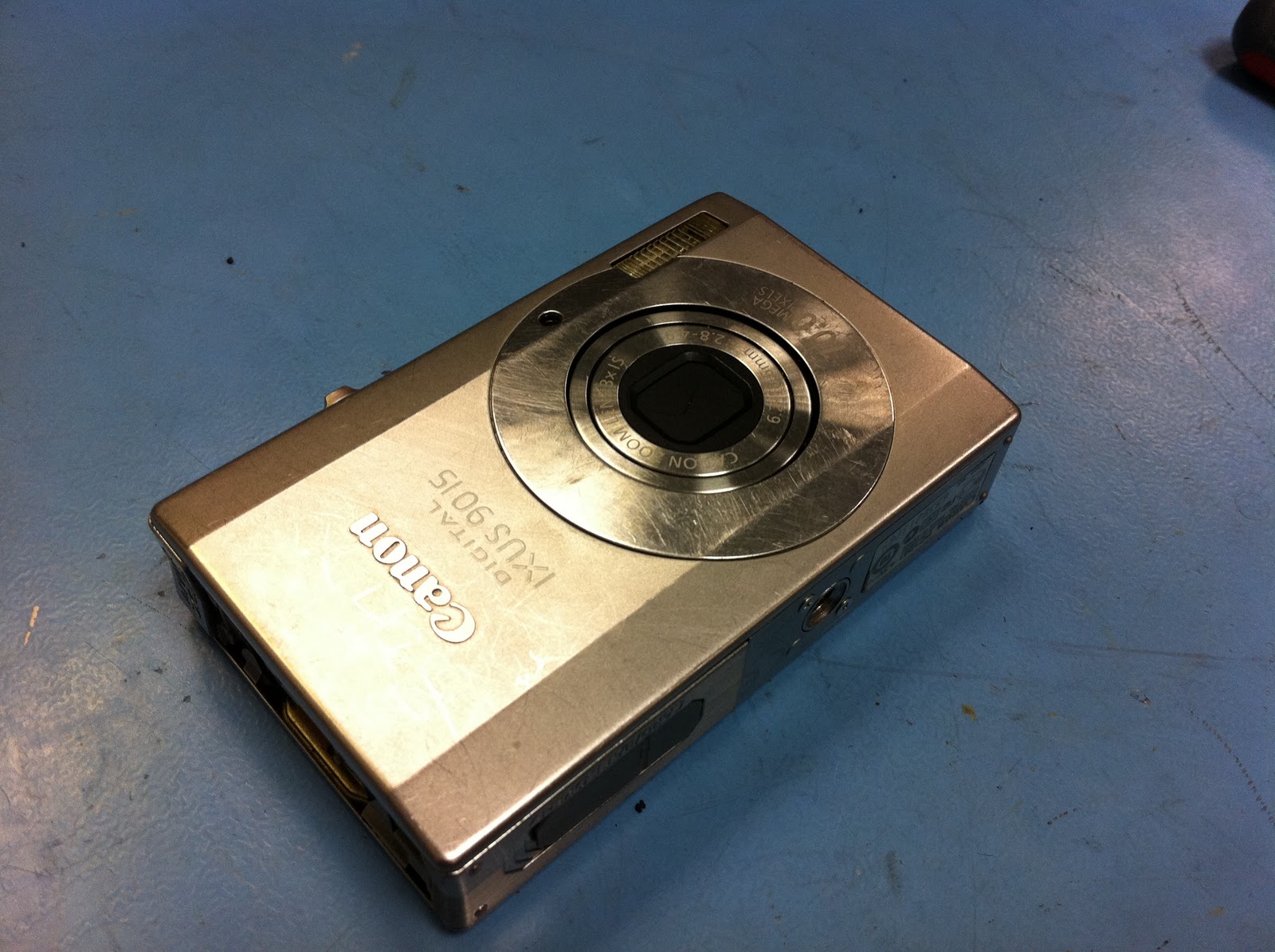
Canon Ixus 90 is camera sand damage

This Canon camera had been left on the beach overnight and would not start up due to the lens being jammed. Everything was very gritty, not good.

I pulled the camera apart, not difficult but due to the intricate nature of its construction not a task to be taken lightly.

There were two motors associated with the optics, one appeared to be for zoom, the other focus. The zoom was a good place to start, some of the gearbox it drives was exposed allowing you to observe it moving, or in this case to let sand in and jam it up. There was also an access opening to drive the gearbox by hand, a nice touch. To get to this properly the optics assembly had to be removed from the camera which involved total dissassembly as the two screws holding it in are obscured by the battery housing.


The manual drive was reluctant and time consuming to move due to the sand in the mechanism, however the lense protection cap started to peek open and the lens extend.

At this point I decide to drive the motor directly with a PSU as it was so time consuming, set to 4v and a modest current limit I applied power and it drove all the way out, this was probably more oomph than the camera would normally apply.

Driving it manually in and out it steadly became more responsive, it didnt sound great though.

I re assembled the camera to see if it would now wake up, it did !

All was not good though, the live image would constantly change brighness with a loud click (sounded like the aperture opening and closing), if you tried to take a shot it would try to focus, make a grining sound and fail to make focus, zoom would work though.

At this point I decided to call it a day. The time and effort required were just not worth it. The optics assembly could in theory be stripped and the contamination removed but I was very confident the camera would never be 100% again which is kind of important if you want it to take good quality pictures.

Filed under unsuccessful but an interesting teardown anyway.

Wednesday, 12 January 2011

Samsung Syncmaster 540n no backlight.

A 15" LCD monitor to look at. Backlight would come on every time at power up for only two seconds then go off.

A few possibilities but a quick google pointed towards......thats right.... PSU capacitors. Id been here before with a Samsung LCD.

The PSU board was slightly different to the one that the google result gave but the culprit stood out for all to see with a bulge on top and a little brown stain. (fitting in nicely with my last post about observational repair !)


Once pulled from the board it measured at 90uf and falling instead of the specced 220uf. Replacement in it was time to check....


Result !

Conclusion, poor quality electrolitic capacitors strike again. (well, its my first blog post to cover them but it wont be the last Im sure).

I would comment the monitor came apart particularly easily, I liked the design.

Tuesday, 11 January 2011

Radio Control Helecopter.

This had been sat negelected for a long time (over a year !)! Cheap radio control helecopters have come on a bit since this model was given to me for repair (and forgotton about !) but I decided to get it done anyway.

Only one of its twin rotors would spin.

The two motors were wired to a dual n channel mosfet package, only one motor spinning tended to indicate one dead mosfet ! It was a FDS8926A (8 pin package just next the red wire closest to the bottom of the pic) , a replacement chip was sourced for <£1 and fitted, the original chip was definitely dead as it had a hole burnt in it ! Observational repair is so useful, no matter how complex a system is, a very very good look can lead to a fix without in depth knowledge of a circuit.


The motor still would not spin ! I swapped the motor wiring over, it drove the other motor just fine so I stripped the non functioning motor.

It was tiny (fortunately not as tiny as the rear rotor !). Inspection showed that one of the tiny leafs of metal that act as brushes to the commutator had vapourised, probably an over current situation took out the brush and mosfet.


I thought this was dead and buried but I managed to re form the contact by bending it differently, the motor now worked and the helecopter was airbourne once again !

Monday, 3 January 2011

Nintendo DS Lite game cartridge slot.

Another DS Lite already ! (another pink one, in fact two).

This time the cartridge slot contacts had been damaged ! in fact two machines were damaged but I only had one donor connector this time.

The pic shows the connector off the board (exposing the usually hidden ARM CPU), I used a huge iron tip and solder braid to clear the tabs, then levered them clear with a scalpel. Then I removed the PCB connectors by flooding with low temp solder (google youtube chipquick for details on the method, or see my first blog post).

I need to order another off eBay, only £1.50 from HK or £4 from UK.